INSIDER
|
|
|
INSIDER |
| 2008-07-24 |
|
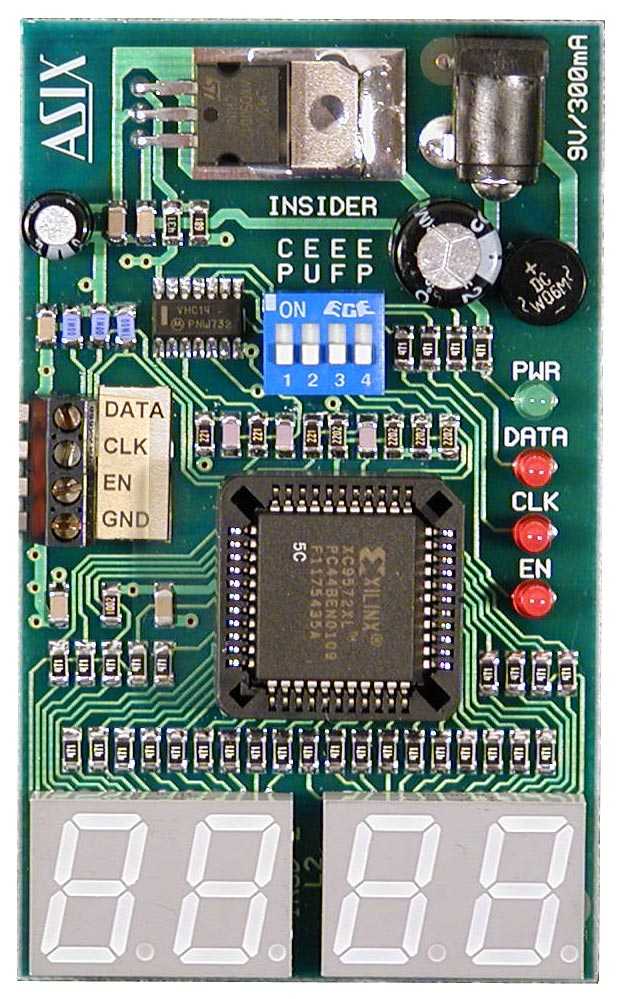
INSIDER is relatively simple but surprisingly useful debugging tool for microcontrollers and Field-Programmable Gate Arrays (FPGAs). The purpose of INSIDER is to monitor the internal device status such as register contents or program position. Even without hardware emulator or any other in-circuit debugger, INSIDER allows the user to analyze the application behavior. User can correct even hard-to-find errors much faster, easier and more comfortable. INSIDER can be used to debug applications with any microcontroller or microprocessor type (Microchip PIC®, Atmel, Dallas, Philips, Motorola, ...) or even FPGAs (Xilinx, Altera ...). The wide input voltage enables user to work even with the low voltage applications e.g. 2.5 V logic. The INSIDER's main advantage is significant increase of effectivity when debugging real-time applications without an emulator or any other debugger. Thanks to low cost, low requirements to the debugged application and time savings is the INSIDER capable to significantly decrease the resulting application development costs. Work with INSIDER is easy and straightforward. The user adds a short code to his/her MCU application or a small state machine to the FPGA application. Two or three pins have to be connected to the INSIDER, but these pins can be shared with other system functions. INSIDER has three inputs: CLK, DATA and (optional) ENABLE. The internal logic contains a configurable 16-bit shift register, configurable 16-bit latch and the binary -> 7-segment code decoder for the 4-digit LED display. Clock input CLK has selectable active edge - rising or falling. There are many option for the enable (EN) input:
The status of all three inputs is indicated with LEDs. The input levels are compatible with these standards: CMOS 2.5 to 5 Volt, TTL and LVTTL. The CLD, DATA and EN signals have Schmitt triggers. There are no special power-up sequences required, both INSIDER and the connected application can be powered on and off arbitrarily. CLK input accepts clock rates up to 50 MHz. Examples (PIC macro, PIC subroutine, FPGA schematics) >>> |
Supported devices
Features
Contents
|
|||
DownloadINSIDER User's Manual (PDF format, 103 kB) |
||||
© ASIX s.r.o., 1991-2012. All rights reserved. |